Vertex Painter with instanced rendering support using texture stored vertex colors
Summary
A Vertex Painter that stores vertex colors within a texture instead of the model. Each texel represents a vertex and its corresponding color. One texture is generated for each mesh that has been painted in a scene (including sub-meshes). Texture file names are identical to the mesh name, however a "_x" post-fix that represents the sub mesh index is also added.
Two binary files are also generated, one of which includes all material binding information, and the other vertex texture UV-coordinate indices. These files are read from on scene load and determine material binding and UV coordinates within the vertex shader.
Premise
When developing one of our game projects at The Game Assembly, one of the artists on the team asked if it was possible to implement a vertex painter within the engine as it would allow them to more easily make tweaks to a levels appearance. I thought it sounded like a great idea so I told them yes! As I started planning out the details, I realized that if I put a unique spin on the implementation I could develop this during my specialization. Which is what I did! The goal was making a functional tool where the painted meshes would not affect the draw call count, and therefore still allow instanced rendering. One of my ideas to solve this was to store all the vertex color information within textures instead of within the mesh instance vertex themselves. This would also allow me to focus more on the engine and graphical implementation, which is the area of development I would like to specialize in!
This text will go through some of the intricacies involed in developing a vertex painting tool that stores all vertices' color information in textures, as opposed to storing it directly within a mesh instance. Since a lot of engine and rendering pipeline changes had to be made to make this implementation work smoothly, most of it won't be mentioned in this text and it will mostly focus on the steps taken to texture mapping, binding and how it is read within the vertex shader.
Topics at hand:
- Converting the mouse position from screen space to world space
- Fetching the mouse hovered entity's ID and its corresponding mesh
- Perform a sphere intersection test on all vertices within the brush radius (previewing intersecting vertices is also be done here)
- Vertex color texture format, mapping and binding
- Brief brush tool customization
Implementation
Mouse position related data collection
To know where the mouse is relative to the hovered entity we need both the entity's ID and the mouse position in world space. Unfortunately we lacked screen-to-ray collection testing support within our engine at the moment of implementing this tool, so a few work arounds were required. Our engine uses a deferred rendering pipeline, and so a few different RTVs are written to when rendering to the G-buffer. Two of these RTVs, the "WorldPosition" and the "Effects" RTV, contains some information that could be used to accomplish this. The world position is self explanatory, however the Effects RTV is a little bit of a special case. It was a R8G8_UNORM RTV, meaning there was room for blue and alpha components that could be used to fit in the EntityID. If we combine these two uint8s into a singular uint16, we can potentially access all available EntityIDs within our scene's current scope. When this was implemented, all data needed from the mouse screen space position could be sampled accordingly.
NOTE: The world position can be reconstructed from the depth buffer and a world position RTV is not needed. However we already had the world position RTV prior to implementing the vertex painter for debugging and convenience purposes, which is why was used in this implementation.
Vertex intersection and preview
Once the mouse world position and hovered entity's ID is fetched, the relative mouse position in model space is then compared to against all vertices within all meshes contained in the entity using the brush radius. This vertex container is updated every time the mouse is moved, and all intersecting vertices are used during brush preview and all future painting operations.
As for previewing all intersecting vertices, screen space decals were originally planned to be used. However due to time constaints, this never came to be. Preview is done using the debug renderer, since it is a render that has a disabled depth stencil state. One quad is then drawn for each intersecting vertex, rotated towards the vertex normal. Though decals were never implemented, this visualization method does make the tool much easier to use!
Vertex color texture format
One of the greatest challenges when creating this tool is deciding on a texture format. My approach to this problem was to assign colors as if they were part of a jagged uint32 array with a size equal to the texture size. Each entry would represent a vertex color and its array location would be based on the SV_VertexID semantic. What's tricky about this however, is knowing where the intial UV location each instance should derive from.
At first I considered linking the initial index to the SV_InstanceID semantic, but discarded that thought since culling would have a severe impact. What I ended up using was giving each entity its own unique index that's incrementally assigned during the painting process. For example, the first painted entity of a mesh type would be given the value of 0 and following entities of the same mesh type would have incremented values of 1, 2, 3 and so on. These indices would then be saved into a binary file that unique per scene, and is loaded once on scene load.
Since the aforementioned indices are related to the EntityID, it does mean that if the EntityID would change due to ID recycling or any scene hierarchy updates that could affect their IDs, the indices would become missmatched. However since vertex painting is done exclusively on static geometry, and only after a scene has been finalized, it never becomes a problem. Though it is something that should be considered should this be implemented in another environment. A possible solution is to track whenever a painted entity is modified (by emitting an event for instance), and rewrite the binary file on scene save to correct these missmatches.
You may notice the +1 when calculating the step offset. Since each step is dependant on the vertex count, I avoided the use of a constant buffer to store the value and instead reserved the (0, 0) coordinate for it. This decision was made early on to aid in debugging and to reduce overhead. Here are some examples on the resulting layout:
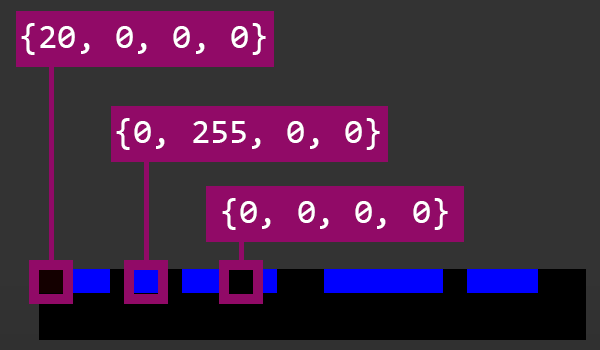
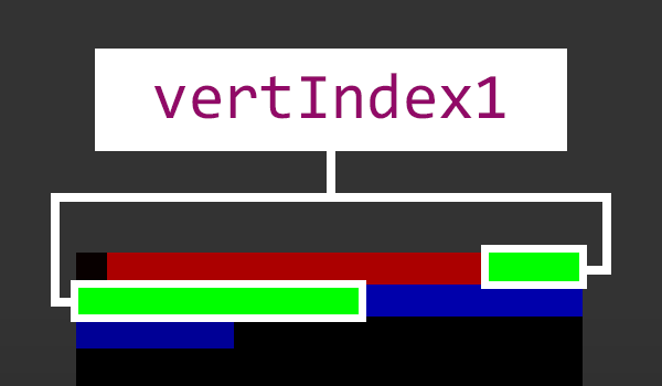
Second image represents how the data gets aligned when the pixel data needs to wrap to the next row.
Vertex color mapping
Once the format is established, all that is left to allow painting is to save the color information to an SRV and have it bound as a vertex shader resource. To do this, I created the vertex texture with the dynamic usage- and cpu write flags enabled during editor mode. Additionally, a staging texture was used for copying data during a write-discard mapping operation to the target SRV.
When saving these textures to distinct .dds files, their files names are identical to the source meshes'. Additionally since a model can contain multiple meshes, this means each sub-mesh is also given its own texture. Due to this a "_x" post-fix is added to the file name, where x is replaced with the sub mesh index. Generated vertex color textures use the R8G8B8A8_UNORM color format, since higher detail levels are rarely needed. It is possible to combine these textures into a larger texture atlas, and although this is not implemented as of writing this article, it is something that will be implemented in the future! The reserved (0,0) slot could also be used for vertex colors instead, since a constant buffer would most likely be needed.
Vertex texture binding
The vertex color output is generated by simply sampling the texture that was generated by the Vertex Painter. Since we are sampling from the texture we already know the format to, the UV locations are calculated the same way as when they were written to the texture. However since the need to get the vertex count, it is also sampled from the reserved (0,0) location.
All vertex color textures are assigned the same dimensions (currently 1024x1024px). However a potential optimization would be to dynamically alter the texture size depending on the amount of meshes that has been painted on. There would also be no need to change any vertex shader or painting logic since they base their indexing off of the texture dimensions at runtime. Though to save time when implementing this tool, this was never implemented.
Material binding
With the pipeline complete, all that is missing is associating materials with each vertex color channel during the painting process. This material information is stored within a binary file that is generated or updated each time the user saves their current changes in the tool. The data contained in these files are:
- Scene names
- Affected meshes' names
- Affected sub meshes' indices and their vertex color channel associated material names
When files are being read from, the material names are bound to each affected mesh prior to rendering if available. The two different binary files (material binding and vertex painted indices) could also be combined into a singular file if needed. With the pipeline complete, the generated file structure looks something like this:
Brush customization
To enable further customization, some brush hardness and color strength options were also added. Hardness refers to a feathering effect, and color strength the base line opacity of the selected color that whilst painting. The implementation is quite simple and is just a distance check with some multipliers.
Here's a showcase on how different brush settings can affect painting.
Results and Final thoughts
A vertex painting tool where all vertex colors are sampled from a texture has successfully been made and the initial goal has been reached! Since they are sampled, the mesh data being sent to the GPU remain the same and therefore the draw calls also remain the same. This way of implementing a vertex painter is quite handy when it comes to debugging since all you have to do is to open a texture file and look at it. Additionally, the performance gains from not mapping too much data to the GPU are also quite nice! Though by having so many different textures, it does induce a penalty, especially to the RAM. This will be somewhat reduced in the future, since they will be combined into a texture atlas.
It is currently quite fragile when it comes to scene hierarchy, which means it can realistically only be used after set dressing is finalized without wasting too much time correcting its issues, so there are definitely room for improvement. All-in-all I am quite happy with the results! I think this take on the instantiation problem is quite unique and it was really fun to implement! c:
Here's an example of the tool in action, showcasing it's usage (it's really just me messing about). The pixel shader used for this showcase simply lerps between the bound material textures, using the vertex colors as the lerp interpolator value. These values are then used on the albedo, pixel normal, material and effect G-buffer output textures.
The painter currently works on an per-entity selection mode, where the user is restricted to painting on meshes they have selected prior to painting (during "Object Selection Mode"). However, if no meshes are selected, it simply paints on the object the mouse is currently hovering over. This is something that could cause issues by accidentally painting on some meshes unintentionally. Though it can be circumvented by forcing the user to select entities prior to painting.
The figure below visualizes how the vertex painter causes vertex colors to only be applied to an affected (painted) area, even when using instanced rendering. The vertex normals without any face culling are shown to more easily showcase the mesh arrangement of the scene. The shown meshes are missing the "roof" because that part of the model is another sub-mesh. These images were gathered using RenderDoc.